Real MicroPython in the browser: BBC micro:bit V1 and an RP2040 board
Two MicroPython boards join the catalog. Write the same code your classroom uses, run it on a simulated board, and drive real breadboard circuits with it.

de:volt can now run MicroPython. Not a look-alike interpreter: the BBC micro:bit V1 runs the micro:bit Foundation's own MicroPython build, and the new RP2040 MicroPython Board runs the official RP2040 MicroPython firmware on an emulated RP2040. Programs you would write at python.microbit.org or for a Pico-class board run here, and their pins drive the same simulated breadboard as every other part. Both boards are available on every plan, including Hobby and guests.
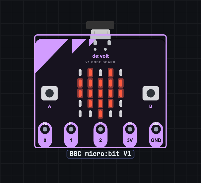
BBC micro:bit V1
Drag the board from the Microcontrollers group, select it, and open the Code tab. from microbit import * works the way your lessons expect: the 5x5 display mirrors live on the board art, buttons A and B are clickable on the canvas (press and hold works too), and the accelerometer, compass, temperature, and light level are all available to code. The five large edge pads are wireable: P0, P1, P2, 3V, and GND. pin0.write_digital(1) puts a real 3.3 V on the net it is wired to, and read_analog() reads back whatever your circuit is doing, 0 to 1023.
Editing never reflashes the board mid-keystroke. Press Run (or Ctrl/Cmd+Enter) to flash, Restart to run the last flashed program again, and pick from built-in examples (show a heart, scroll text, buttons, tilt) to start from something working. The program saves with the circuit, and clicking the USB connector plugs and unplugs board power.
RP2040 MicroPython Board
The RP2040 board is a 40-pin, DIP-style board that plugs into a breadboard straddling the centre gap, with the pinout printed along both edges: GP0 through GP22, GP26 to GP28 with real 12-bit ADC behaviour, 3V3 out, VSYS, VBUS, and eight grounds. GP25 drives the on-board LED, like the dev boards it resembles.
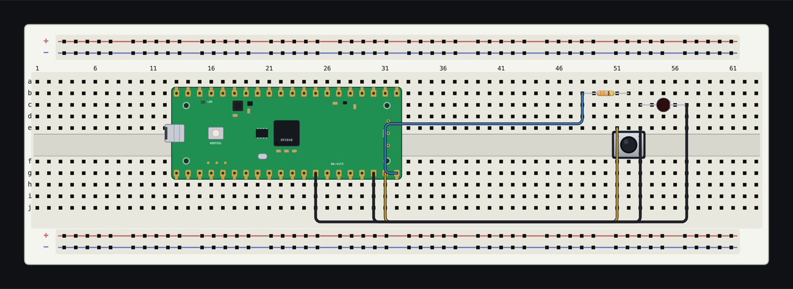
from machine import Pin, PWM, ADC all behave, PIO programs run, and the emulation is at the silicon level, so timing-sensitive tricks generally survive. The Code tab ships examples for the on-board LED, an external LED on GP15, a button on GP14, and reading a potentiometer on ADC0.
Two things to know honestly. RP2040 GPIO is 3.3 V logic and is not 5 V tolerant, in the simulator as on the bench. And a full RP2040 emulation is real work for your machine: on modest hardware a busy circuit can drop below real-time speed, which the status pill will tell you plainly.
Fixes and improvements
- Polarized two-lead parts (LEDs, diodes, electrolytic capacitors) show + and − chips above their legs on hover, and breadboard LEDs paint a cathode-side flat bar.
- The Arduino UNO board art was redrawn.
- USB connector animations landed for all boards that have one.
Pinouts, powering rules, and supported APIs are documented for both boards: docs.devoltapp.com/parts/microbit and docs.devoltapp.com/parts/raspberry-pi-pico, with the shared editor workflow at docs.devoltapp.com/parts/writing-micropython.